How to assemble VSAT antenna feed
See also cross-pol OMT and co-pol diplexer filter / feed assemblies
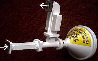
This assembly is designed to transmit on one polarisation and receive on the other. As shown, transmit polarisation is vertical and receive horizontal. To change this turn the whole unit through 90 degrees. In actual satellite service that the assembly will be tilted to some calculated angle and set to an accuracy of +/- 1 deg. Start with the feed set to receive nominal horizontal or vertical and then turn the feed clockwise if the polarisation angle is positive number, while facing the satellite.
Attach the Low Noise amplifier/Block down-converter (LNB) at the top sidearm waveguide. Attach the transmitter or transmit waveguide to the left end o of the centreline waveguide. In both cases take care that the rectangular holes align correctly, as do any gaskets used.
Inside the Ortho Mode Transducer (OMT) assembly, where two rectangular waveguides are merged into a circular waveguide, is a horizontal metal vane across the waveguide that stops horizontally polarised receive signals passing. These signals are forced up through a slot into the upper filter assembly and thence into the LNB via a 90 deg H plane bend. (remember H = hard to bend!)
| Vertically polarised transmit signals pass through the whole assembly along the centreline. |
|
Vertical polarisation refers to the tiny vertical half dipole pin that sticks up through the broad face of the rectangular waveguide. |
Filters are incorporated to stop leakage of the transmitter output into the low noise receiver. If this happens the noise floor increases, the gain reduces and in the worst case the LNB is permanently damaged (burned out). If you have no receive signal and a dead LNB, don't keep replacing LNBs and blowing them all up. Test replacement LNBs with the transmitter off. There must be a filter in front of the LNB to protect it.
The feed horn shown is Model 0800-1375 39 deg Ku band horn. The outside diameter of the feed is 14.6 cm (5.76 inches). Feed opening diameter 12.75 cm. Length 10.9 cm. It is intended for use with f/d=0.8 ETSI antennas such as 1134, 1194, 1244, 0800-1362(1.2), 0800-1474(1.8) Frequencies: Receive 12.25 - 12.75 GHz, transmit 14 - 14.5 GHz
Note that a smaller feed horn exists called 0800-309. Outside diameter 13.3 cm.(5.23 inches). Feed opening diameter 11.2cm. Length 9.1 cm. This is intended for f/d=0.6 antennas such as 1123, 1124, 1125, 1183, 1184, 1251, 1255, 1381, 1383.